The seemingly simple yellow, black, red and white lines on an aircraft stand are not so simple in how they are marked. Ramp layout is a technical topic and each ground marking on the ramp is made after careful measurement and technical consideration.
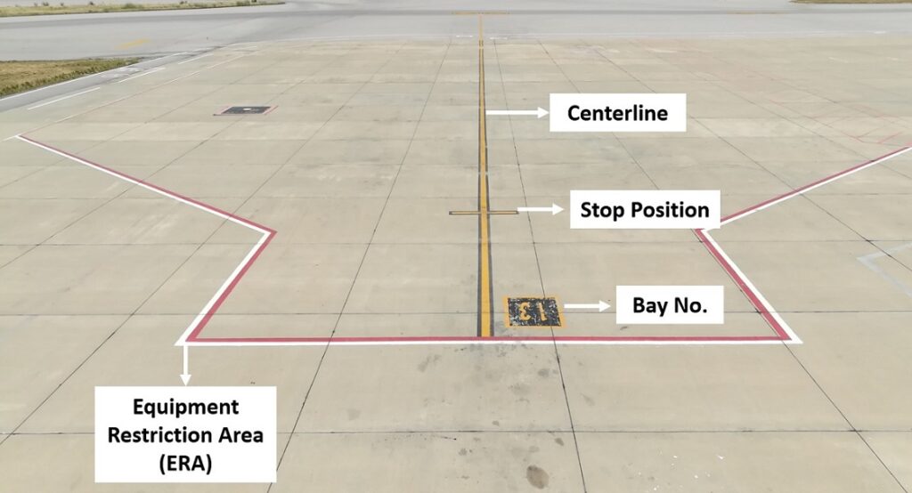
In this article, we are going to explain the ramp layout and the technical considerations that go behind each of the ground markings on an aircraft stand. In order to get a sense of what we are dissecting in today’s article, take a look at the finished product below.
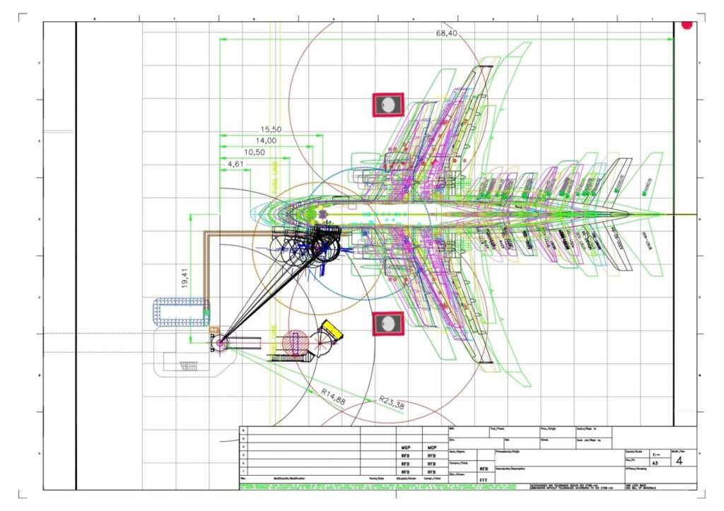
These measurements are worked out after an engineering design evaluation based on safety assessment of aircraft parking not only on that ramp but also of neighboring ramps (a.k.a aircraft stands or bays).
Ramp layout is scientifically significant and interesting such that understanding of ramp layout evolves into understanding of airport’s apron design; parking capacity of airport for aircrafts and compatibility of airport with different aircraft geometries. If you understand the science behind ramp layout, you can understand all of these important airport design aspects.
So without further due, let’s jump right into the topic.
Basic Ramp Layout
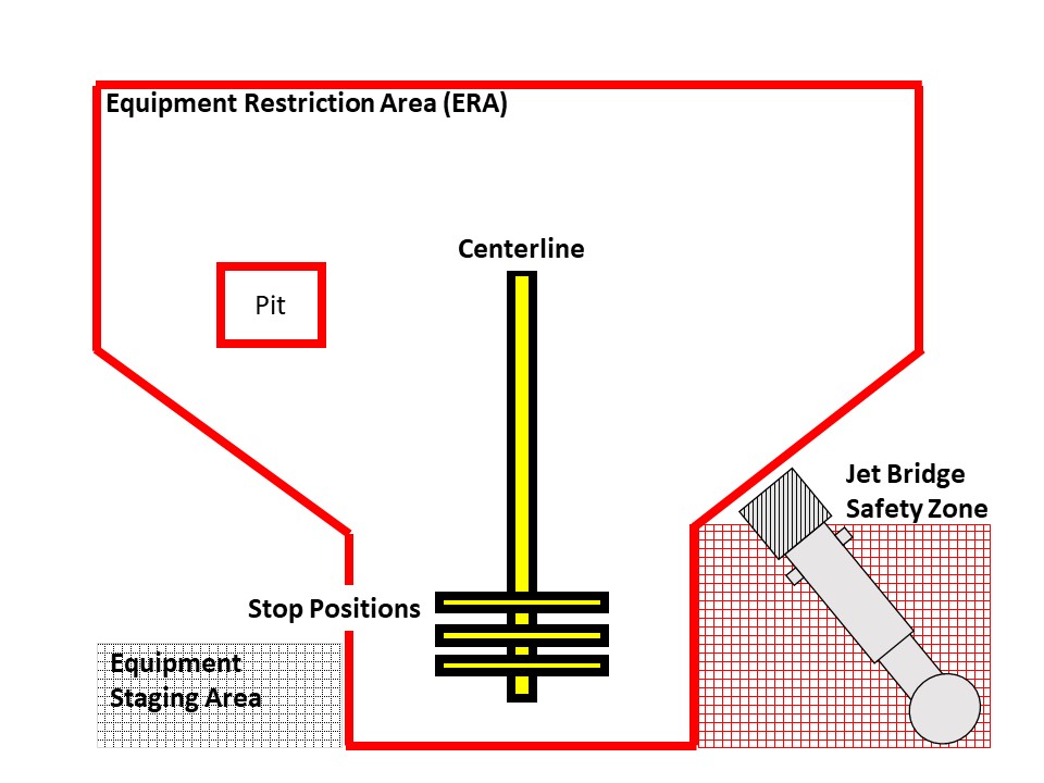
The line running along the length of the ramp and symmetrically dividing the ramp into two halves is the aircraft or ramp centerline. The centerline is meant for pilots to keep the nosewheel of the aircraft over it while the aircraft is rolling on the ramp for parking. This line is marked on ground with a reflective paint for ensuring high visibility for the pilots as well as the ground handling staff.
The set of lines marked perpendicular to the centerline towards its end are called aircraft stop positions. The stop positions (as the name implies) are meant for pilots to apply brakes of the aircraft when the nosewheel reaches the specified stop position. Like the aircraft centerline, they are also marked with reflective paint for high visibility.
The boundary around the centerline loosely resembling an aircraft’s shape is called the Equipment Restriction Area (ERA). It is also called Equipment Restraint Area, Aircraft Safety Envelope or Aircraft Safety Area. It defines the boundary within which no person or object must be present when the aircraft is rolling on the ramp and approaching its stop position.
After the aircraft has parked and its engines are turned off, different machines and vehicles can enter this safety envelop to perform their respective operation. However, as soon as their operation or task is finished, they must be removed from the safety envelop.
There must be no vehicle parked inside this safety envelop unless it has something to do with the aircraft. In short, this safety envelop must remain clear of any unnecessary piece of equipment, machinery, vehicle, objects and humans before, during and after aircraft parking.
The area adjacent to Equipment Restraint Area (ERA) with ground markings for ground support equipment is the Equipment Staging area. It is also known as Equipment Parking Area or Equipment Holding Area. It is the area where Ground Support Equipment (GSE) are supposed to park before and after their job (which is the specific ground support operation each machine performs).
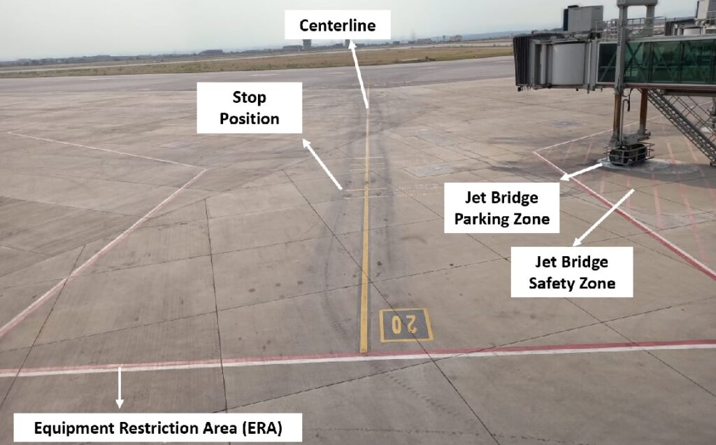
For all aircraft stands where jet bridges (or passenger boarding bridges) are installed, jet bridge safety or movement zone and jet bridge parking zone is also marked on ground.
Jet bridge safety zone defines the area where no vehicle, machine or piece of equipment is allowed to remain as it poses risk of collision between that object and the jet bridge during movement. Even when the jet bridge is not operated, this safety zone must remain clear of any parked vehicle or piece of equipment.
Jet bridge parking zone defines the home position or parking position of the jet bridge. It is the area where jet bridge wheels must remain positioned when the jet bridge is not in use. Jet bridge moves from this parking zone when it needs to engage with the aircraft. Similarly, after boarding of passengers is completed, jet bridge needs to be returned to the same parking zone after disengagement from the aircraft.
Technical Explanation of Ramp Centerline
Its purpose is to keep the aircraft centered on the ramp during the parking process otherwise there is no reference for pilots to keep the aircraft straightly aligned. This alignment is necessary for the aircraft for multiple safety reasons.
The first is to ensure a safe separation between the wingtips of the aircraft being parked on the ramp from wingtips of the aircrafts parked on the adjacent ramps (or aircraft stands).
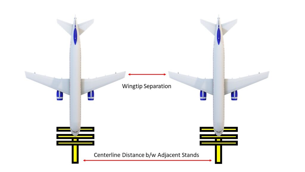
The second is to and allow different ground support equipment to safely connect and move around the aircraft. This purpose is fulfilled in conjunction with aircraft stop position (which we will discuss shortly).
When pilots approach the ramp, the nosewheel of the aircraft remains on this centerline as the aircraft rolls over the ramp until it reaches its designated stop position.
Technical Explanation of Stop Position
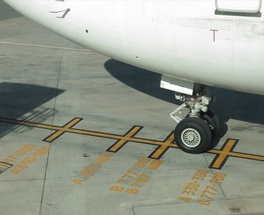
Stop position is marked perpendicular to the centerline to indicate where the aircraft will finally apply its brake and stop. Aircraft’s nose wheel needs to be on the point of intersection of centerline and stop position when the aircraft finally stops for parking on the ramp.
There is need for more than one stop position because different aircrafts have different geometries. If you stop the nosewheel of all aircrafts on a single stop position, their rear landing gears, wings, engines, tail, fuel receptacles and other ground service connection points will end up at different places because of varying geometries.

However, what’s needed is that:
- The wing and engine of each aircraft remain safe distance away from other structures/objects on the ramp such as jet bridges
- Ground servicing connections remain accessible for ground support equipment (GSE) especially the aircraft door remains within the reach of jet bridge
- Rear landing gears remain clear of any pit systems available on the ramp
- The aircraft tail remains within safety clearance from the taxiway.
One stop position cannot place all the different parts of different aircrafts at exactly where they are needed with respect to safety clearances. Therefore, multiple stop positions are marked on ground where each stop position is generally able to park selected few aircraft types.
So for example, if a ramp is able to accommodate 15 different aircraft types, it may have 3-4 stop positions each able to park 4-5 aircraft types.
In short, while centerline safely positions the aircraft along its width, stop position safety positions the aircraft along its length.
Technical Explanation of Equipment Restriction Area (ERA)
Equipment Restriction Area (ERA) is a safety envelop marked on ramp that serves as a safe boundary around the aircraft parked on the ramp. There must not be any vehicle, machinery or any piece of equipment standing inside this safety envelope when the aircraft is approaching its stop position.
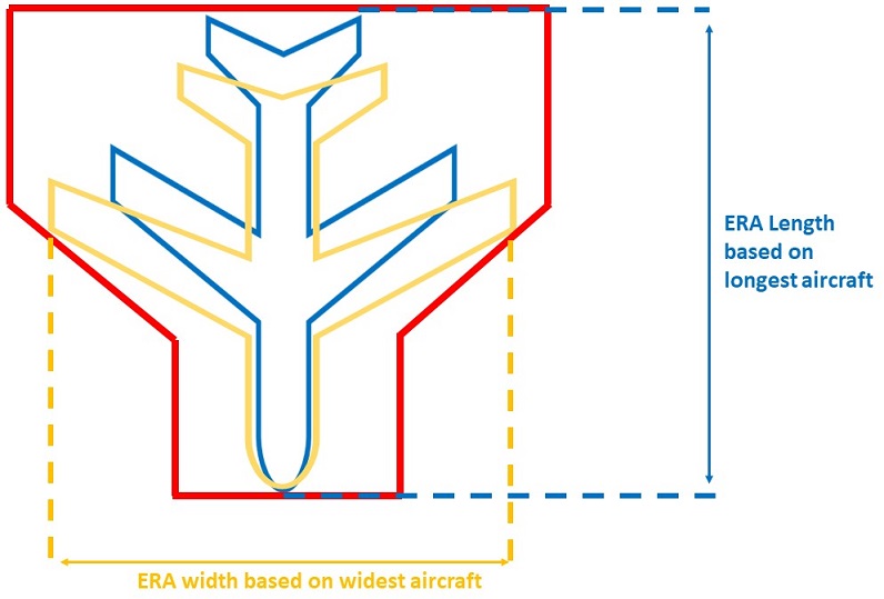
This boundary is marked after considering all of the different aircraft types designed to be parked on the ramp. The width of the Equipment Restriction Area (ERA) is based on the wingspan and fuselage diameter of the widest aircraft to be parked on the ramp.
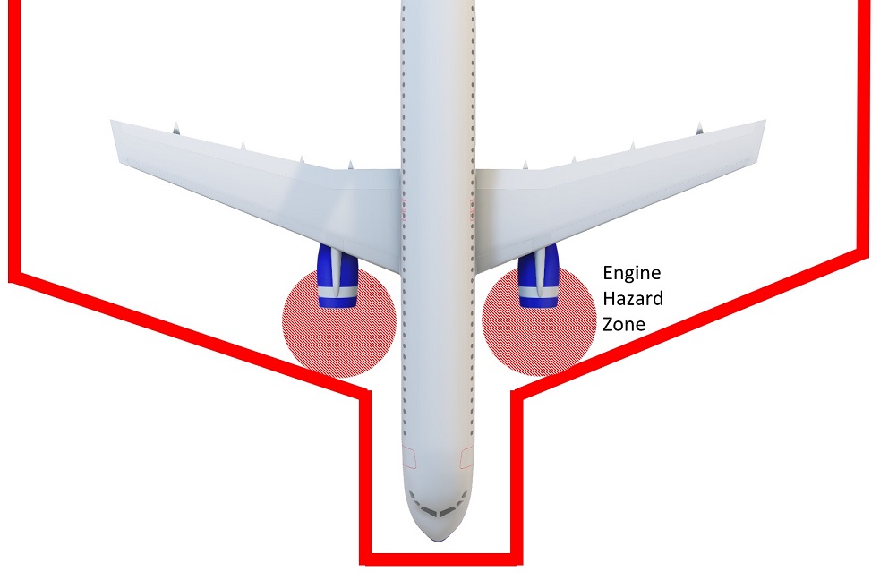
Similarly, the length of the Equipment Restriction Area (ERA) is based on the length of the longest aircraft. The inclined boundaries are based on the wing geometry and the greatest engine suction hazard zone of all aircrafts to be parked on the ramp.
Technical Explanation of Jet Bridge Safety & Parking Zone
Understanding jet bridge safety zone is simple. Since jet bridge is a heavy duty piece of movable equipment, an area is marked on ground for safety during its movement. It is necessary to prevent jet bridge running over or colliding with any object or person causing an accident.
The jet bridge parking zone is more technical in nature. When the aircraft is rolling on the ramp to reach its stop position, all other equipment and objects can be removed from the ramp except for jet bridge. It cannot be removed from the ramp. Therefore, it becomes necessary that the ramp layout accounts for this constraint. It does so by defining a carefully evaluated parking zone for the jet bridge.
The location of this parking zone on the ramp is subject to three important technical considerations. The first is that jet bridge is located in the path of the aircraft wing and engine. Therefore, jet bridge’s parking zone keep the bridge safe distance away from the wings and engine of the approaching aircraft.
Second, when the aircraft reaches the ramp and is rolling on the ramp for parking, its engines are on. When the engines are on, the engine suction hazard zone comes into play. It becomes necessary to not only create safe physical separation between the jet bridge and the aircraft but also account for the suction hazard distance of the jet engines. The parking zone of the jet bridge addresses this aspect as well.
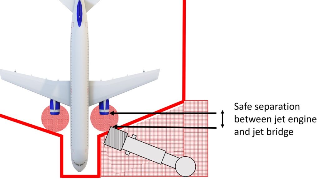
Third, often times jet bridge has to move in an arc path to engage with the aircraft door. Under such a condition, the parking zone of the jet bridge is supposed to make sure that none of the aircraft body parts fall in the path of this arc. The jet bridge parking zone is marked after considering how the jet bridge will make its path to the aircraft door.
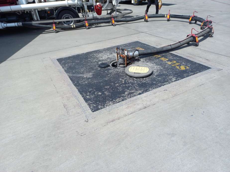
Lastly, if there are any pit systems on the ramp like a fuel hydrant pit, it is also marked with indicative ground markings as visual cues to anyone passing by for observing precaution and ensuring alertness and safety.
In this way, the seemingly simple lines and markings on an apron carry a lot of technical considerations. Each type of marking has its own specific purpose on the ramp for safety of ramp operations. The choice of where these lines will be drawn are subject to geometrical evaluations and safety clearances defined in international standards.
If you are interested in obtaining a base level knowledge about ramp safety, check out this 7-hour video based course on Udemy that you can easily finish in a week (or binge watch in a day or two). It explains ramp safety in detail with interesting case studies of ramp accidents for in-depth understanding of the subject. It also explains ramp safety aspects associated with 13 main ground handling operations carried out on the ramp.